

Learning Objectives
After completing this tutorial, you should know how to:- Define a layout file that compiles code for multiple PEs
- Copy data to and from multiple PEs on the device
Example Overview
Your program will now run on four processing elements (PE). This tutorial demonstrates the program with a simulated fabric consisting of an 11 x 3 block of PEs. For this program, each PE performs the exact same work; that is,A, x, and b are copied to each of
the four PEs, the four PEs each perform a GEMV,
and then the result y is copied back from each PE.
pe_program.csl does not change.
Only layout.csl needs to be modified to assign it to
multiple PEs.
The host code also needs to be modified to copy to and from
multiple PEs instead of just one.
Problem Steps
Visually, this program consists of the following steps: 1. Host copies A, x, b to four PEs on device.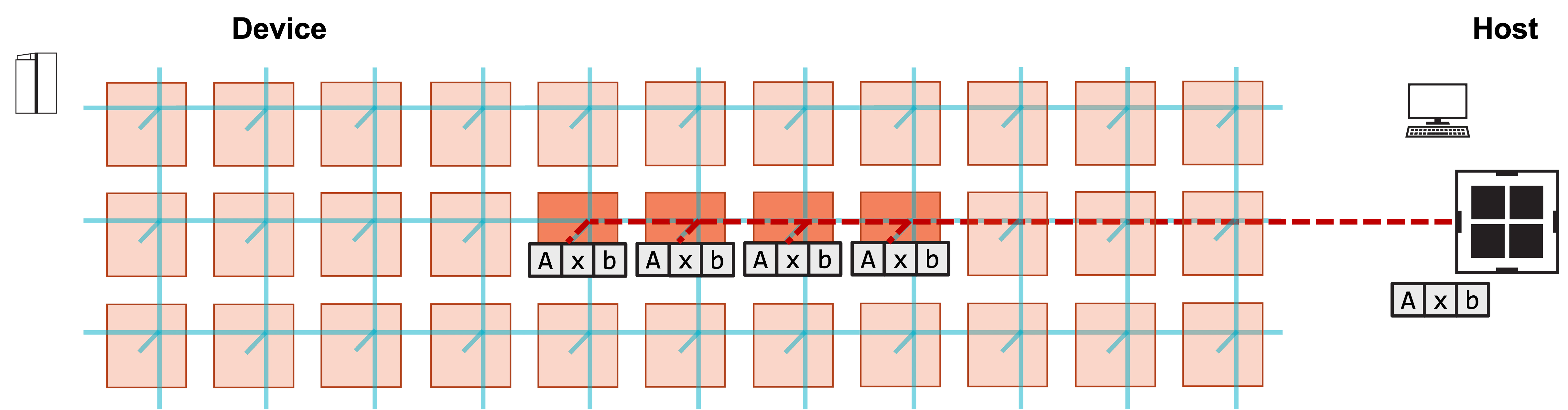
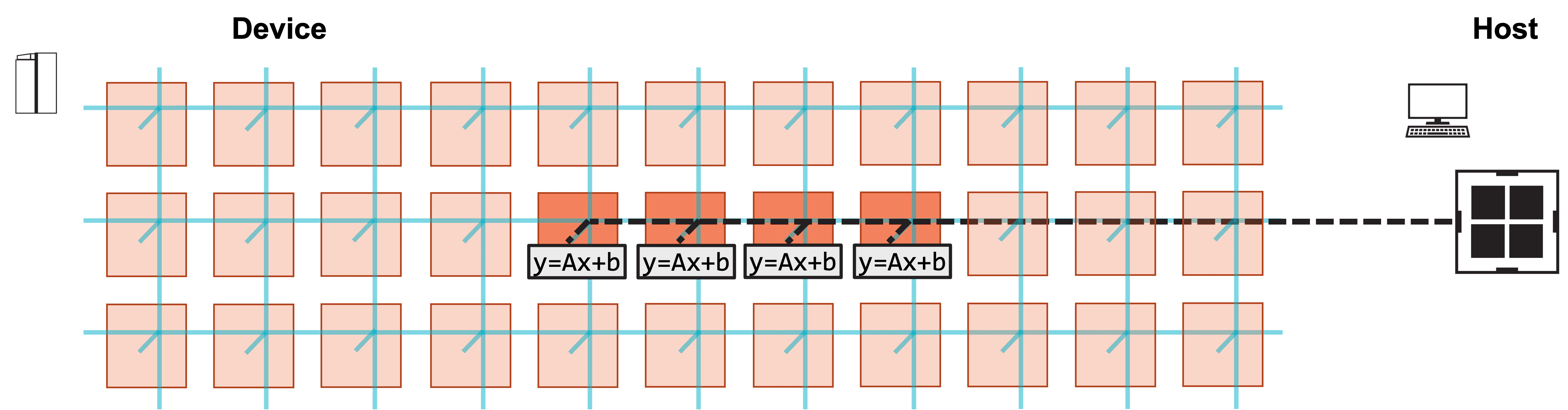
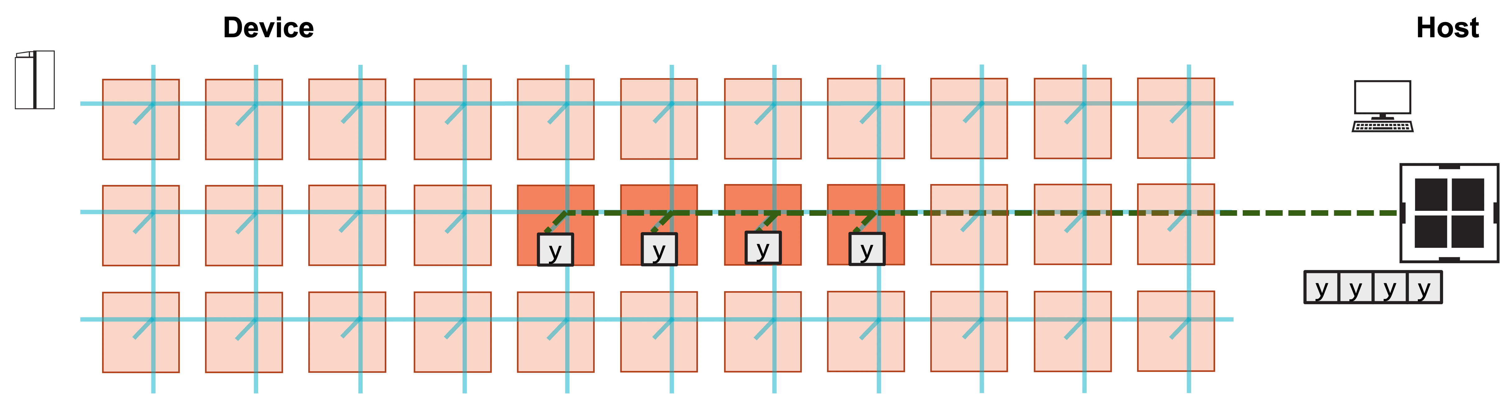
Modify the CSL
How does the layout file need to change to support running the program on multiple PEs?- Modify
@set_rectangleto reflect the new program rectangle. - Modify the
memcpyinfrastructure to reflect the use of multiple PEs. - Call
@set_tile_codefor each coordinate inside this program rectangle.
pe_program.csl remains largely the same; it’s simply assigned to
more PEs.
The new layout.csl is included below, with the changes highlighted.
width is defined,
whose value is set in the compile command.
This value sets the number of PEs in the
row of PEs used by the program.
When <memcpy/get_params> is imported, width
specifies the width of the program rectangle for which memcpy
infrastructure will be generated.
The height is still 1.
Inside the layout block, the program rectangle is now
specified with @set_rectangle(width, 1).
For each of the PEs in this rectangle, @set_tile_code must be called,
so this happens in a loop.
The loop coordinate is the PE’s x-coordinate, or column number,
which is needed to set the correct memcpy_params for each PE.
Modify the Host Code
The host code must now copyA, x and b to multiple PEs,
and must copy back y from multiple PEs.
Take a look at how the memcpy_h2d and
memcpy_d2h calls in run.py need to change:
width.
The host code uses this to specify how many PEs it must copy tensors
to and from.
Now take a closer look at the memcpy_h2d calls:
A, x, and b needs to be copied to each PE in the program
rectangle.
But memcpy_h2d does not perform a broadcast;
it takes its input array and distributes it within the region of interest (ROI)
based on the order parameter.
Here, np.tile duplicates each array width times.
In the first memcpy_h2d, the input array np.tile(A, width) is a 1D
array formed by duplicating A width times, so the full input array’s
size is M*N*width.
The ROI is specified by 0, 0, width, 1, meaning the copy goes to a
row of width PEs beginning at PE (0, 0).
M*N elements are copied to each PE.
Because the order is ROW_MAJOR, the result is that PE (0, 0) receives
the first M*N elements of the tiled array, PE (1, 0) receives
the next M*N elements, and so on.
Thus, each PE receives an identical M*N elements corresponding
to a copy of A.
When y is copied back from the device, memcpy_d2h proceeds similarly:
y_result has size M*width, since each of the width
PEs copies back the M elements of y.
The copied-back result is tested for correctness across all PEs by comparing
y_result to a tiled y_expected.
See A Complete Program for an explanation of the remaining
arguments.
Compile and Run the Program
This compile command adds one additional compile time parameter to specify the width of the program rectangle:SUCCESS! message at the end of execution.
Exercises
In this program, each PE is computing an identical GEMV. Modify the program so that each PE receives different values for the input tensorsA, x, and b, and check
that the computed outputs y are correct.