

The WSE at a Glance
The WSE is a wafer-parallel compute accelerator containing hundreds of thousands of independent processing elements (PEs), interconnected in a two-dimensional mesh on a single silicon wafer. Each PE has its own memory, program counter, and executable code, and communicates with its neighbors by sending and receiving 32-bit messages called wavelets in a single clock cycle. Each PE also has dataflow control: an instruction can terminate the currently running task, at which point the hardware selects the next runnable task — one that has been activated and unblocked (covered in Programs and Tasks below). Incoming wavelets travel along virtual channels called colors; congestion on one color doesn’t block traffic on another. The Cerebras System (CS) is a self-contained rack-mounted system that houses a single WSE, along with its packaging, power, cooling, and I/O. It connects to a host CPU cluster over parallel 100 Gigabit ethernet. Throughout this documentation, the CS is called the “device,” the host CPU cluster the “host,” and the ethernet connection “host I/O.” The SDK uses host I/O to move data between host and device and to launch functions on the device — the figure below shows the mesh of PEs and how they connect to the outside world.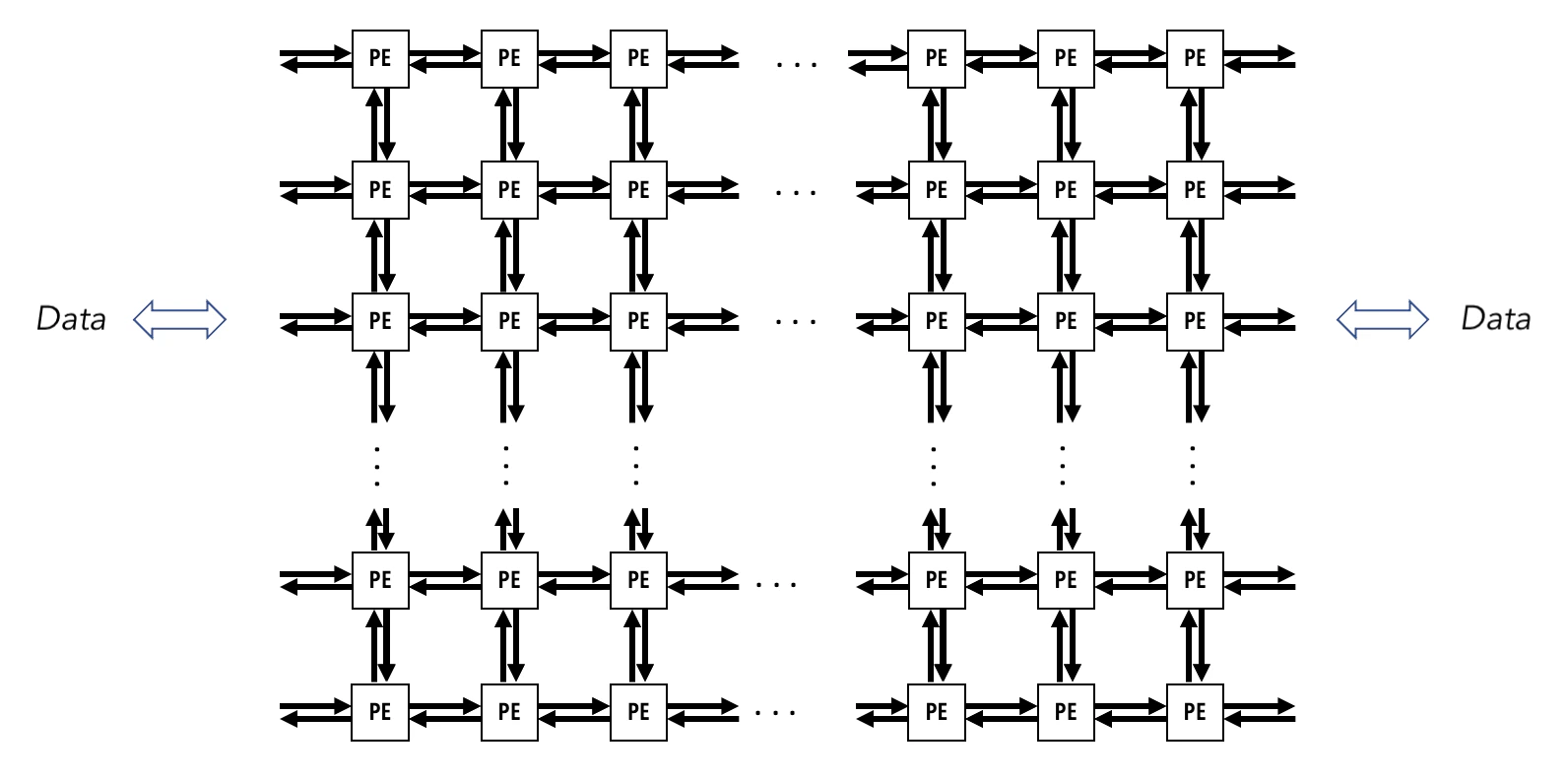
Processing Elements
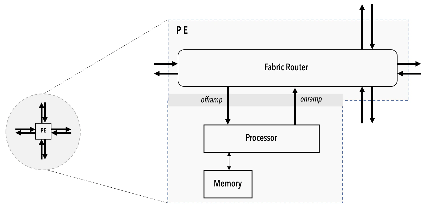
A PE contains three key elements:- A processor, also referred to as a compute engine (CE).
- A router, directly connected via bidirectional links to its own CE and to the routers of the four nearest neighboring PEs in the mesh. The link to its own CE is called the RAMP, and the links to the four neighboring PEs are referred to by their cardinal directions. The router is the only communication device the PEs use to send and receive data.
- The local PE memory where all of the PE’s data and code are stored. Neither the CE nor the local memory of a PE is directly accessible by other PEs.
The Programming Model
To develop code for the WSE, you write device code in the Cerebras Software Language (CSL), and host code in Python. You then compile the device code, and run your program on either the Cerebras fabric simulator, or the actual network-attached device. The host code is responsible for copying data to and from the device, and launching discrete programs referred to as kernels. CSL gives you full control of the WSE. The following sections introduce the key concepts you’ll need to structure device code in CSL.Programs and Tasks
A CSL program consists of one or more subprograms. Some of these are callable functions, and some are tasks. A task is a procedure that cannot be called from other code. Rather, tasks are started by the PE hardware and run until they complete. At that point, the hardware chooses a new task to run. Tasks cannot be called, only activated. They cannot return values. For example, in this code snippet,main_task will set the value
of the global variable result to 5.0 when it is activated and runs.
In CSL this task is represented as:
Task IDs and Types
The term “task identifier” or “task ID” is used to refer to a numerical value from 0 to 63 that can be associated with a task. Within this range there are two properties that further distinguish a task ID: routable and activatable. There are three types of tasks, each with an associated task ID handle type:- Data tasks are associated with a
data_task_id, which on the WSE-2 architecture is created from a routable identifier associated with a color. On the WSE-3 architecture, adata_task_idis created from an input queue, which also must be associated with a color. An input queue is a hardware buffer where data is temporarily stored before entering the compute engine (CE) of a PE. - Local tasks are associated with a
local_task_id, which is created from an activatable identifier. - Control tasks are associated with a
control_task_id, which can be created from any identifier, including those that are neither routable nor activatable.
- On WSE-2, task IDs 0 to 23 are the routable task IDs, as data task IDs are created from one of the 24 routable colors (see below).
- On WSE-3, task IDs 0 to 7 are the routable task IDs, as data task IDs are created from one of the 8 input queues.
Communication
The WSE provides efficient, fine-grained communication between PEs. A PE must be able to quickly, within a few cycles, respond to the arrival of a wavelet, update its internal state, and send out wavelets. The hardware uses 24 virtual communication channels, called routable colors or simply colors, to pass wavelets between PEs. Each color has an ID between 0 and 23. Each wavelet has a 5-bit tag that encodes its color. This color determines both the wavelet’s routing through the fabric and what task, if any, will consume the wavelet when received. (On WSE-3, the consuming task is determined by which input queue the color is bound to; see@initialize_queue.)
In the following code block, the task now takes an argument, named wavelet_data.
This task is an example of a data task.
The builtin CSL function @bind_data_task creates a binding between
a task ID associated with the color
of the incoming wavelet and the task main_task.
On WSE-2, this task ID is the same as the color ID:
it takes on a value between 0 and 23.
On WSE-3, this task ID is instead the ID of an input queue which is bound to the color:
it takes on a value between 0 and 7.
When a red wavelet arrives, the task main_task is activated,
which allows it to be selected by the task picker.
The red wavelet sits in a buffer until the task picker
selects the associated task main_task,
at which point the wavelet is moved into a register so that the task
can get instant access to that data.
Syntactically, the wavelet’s data is an argument of the task.
main_task is also called a wavelet-triggered task,
since it is activated by the arrival of a wavelet.
Note that the @bind_data_task operation occurs within a
comptime block: everything in a comptime block
is evaluated at compile-time.
Colors can also be used in a manner such that wavelets arriving
along the associated virtual communication channel do not activate
a task, but are received by a construct known as a fabric DSD.
The coming tutorials explore this usage.
Task Activation and Control Flow
As shown above, a task becomes available for selection by the task picker when its associated task ID is activated. The task in the above block was a data task bound to adata_task_id,
associated with a color which defines a route taken by wavelets
tagged with that color.
You can also create tasks that do not take wavelets as arguments,
and instead are explicitly activated by other tasks or functions.
These are called local tasks, and the associated task ID type
is local_task_id.
On WSE-2, you can create a local_task_id from the range of task IDs
0 to 30. These IDs are the activatable IDs.
On WSE-3, you can create a local_task_id from the range of task IDs
8 to 30.
In the following example, main_task activates the task ID foo_task_id.
This task ID is bound to foo_task, and so activating foo_task_id
will cause foo_task to execute next.
Block and Unblock Tasks
You can also block a task ID to provide further control over task execution. A task must be unblocked and activated for it to be scheduled by the task picker. If a task is activated while blocked, it will not run until it has become unblocked. By default, all IDs are unblocked and inactive. The following example introduces one additional task,bar_task, and blocks
its ID at compile time with @block(bar_task_id).
When main_task executes, it activates both foo_task_id and bar_task_id.
However, because bar_task_id is blocked, foo_task always executes first.
When foo_task executes, it unblocks bar_task_id,
allowing bar_task to begin execution once foo_task finishes.
If bar_task_id were not blocked at compile time, then the
execution of foo_task and bar_task could occur in any order.
Layout
Layout blocks are how you connect up the multiple PEs in your program rectangle in a way your computation requires. For example, see the following 2-PE rectangle: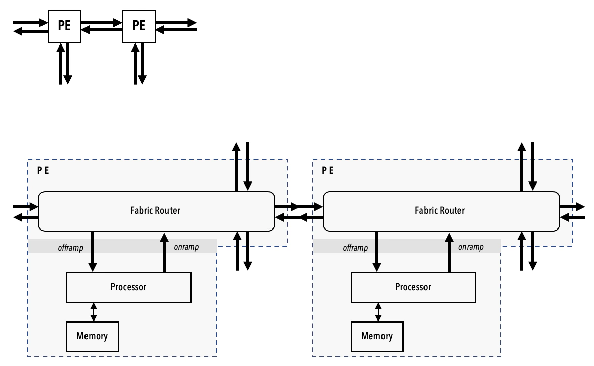
layout block showing a layout of two PEs in a single row:
@set_tile_code() builtin CSL function specifies the .csl file
containing the program for the individual PE within the program rectangle
denoted by the indices in the first two parameters of the function.
For example, the program send.csl contains the task description
that only the PE at the coordinate (0, 0) will perform.
Each user program can define only one layout, specifying a rectangle of active PEs
and a code file assigned to each PE. This layout must be defined at compile time,
and a user program cannot define multiple layouts.
Hence, zero or multiple
@set_rectangle() calls are illegal.Additionally, the built-in @set_tile_code() must be called after @set_rectangle().@set_tile_code() calls after a single
@set_rectangle(),
with each @set_tile_code() function call specified with a separate .csl file.
The @set_color_config calls assign the routing associated with main_color for each PE,
from the perspective of the PE’s router.
For instance, the router of PE (0, 0) will receive wavelets along color main_color
from the RAMP, which connects the router to the CE.
It will then transmit wavelets to the EAST, where it will be received by the router
of the neighboring PE.